

Piezo Nano-Rotation Stage Applied to Factory Calibration of High-Precision IMU
Behind the precise hovering of UAV and the smooth cornering of autonomous vehicles lies a crucial core processor - the Inertial Measurement Unit (IMU). Its precision directly determines the accuracy with which intelligent devices perceive their own postures. The outstanding performance of a high-precision IMU is inseparable from the most crucial process in the production stage: factory calibration. When the calibration requirements of IMU enter the micro-arc era, the piezo nano-rotation stage, with its unique technical advantages, becomes the ideal partner for calibration applications.
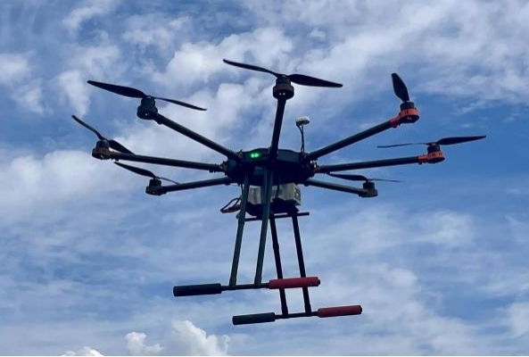
(Note: Image from online resources)
I. Why is IMU Calibration a "Compulsory Course"?
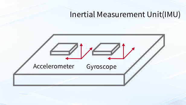
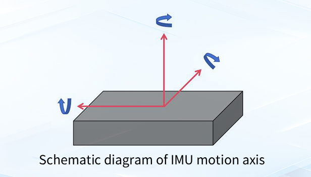
An Inertial Measurement Unit is a sensor device used to measure the motion state of an object. An IMU is typically composed of an accelerometer and a gyroscope. The accelerometer is used to measure the linear acceleration of an object in three orthogonal directions. Gyroscopes are used to measure the angular velocity of an object around three orthogonal axes. By processing these acceleration and angular velocity data, the IMU can calculate information such as the object's attitude, velocity and position.
IMU features a high update frequency and high calculation accuracy within a short period of time. It does not rely on external signals and can operate independently in environments with limited GPS signals, such as indoors, underground, and underwater. Therefore, it is widely used in numerous fields including aerospace, unmanned aerial vehicles, self-driving cars, robots, and smart wearables.
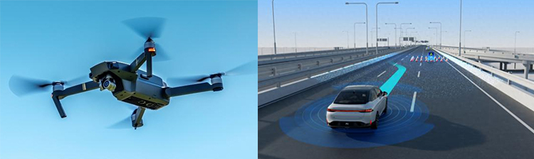
(Note: Image from online resources)
The accelerometer and gyroscope integrated inside the IMU measure linear acceleration and angular velocity respectively. Due to the influence of some factors, there will be slight deviations in the actual output data: it may be errors caused by installation, it may be nonlinear errors of the scale factor, or it may be deviation in the measurement direction caused by misalignment between axes. The essence of calibration is to establish an error model through precise testing, compensate and correct these systematic errors, thereby ensuring that the output data of the IMU is closer to the real motion.
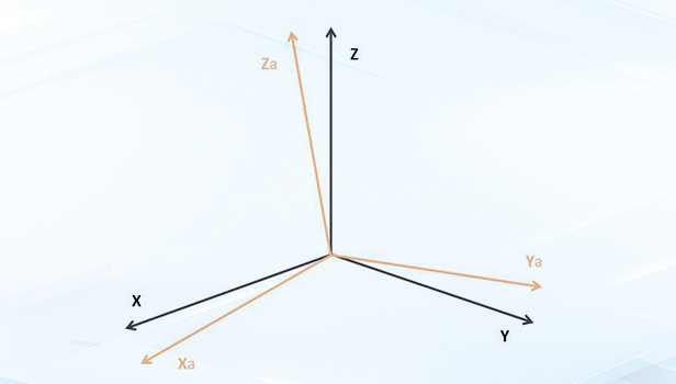
Schematic diagram of the error model
Accelerometers are usually calibrated relying on the gravitational constant: the direction of the gravitational vector is fixed. By placing the IMU in different positions and collecting the output values of the accelerometer at each position state, and comparing the deviation between the theoretical value and the measured value, the zero offset and scale factor and other errors of the accelerometer can be calculated, and the calibration of the accelerometer can be completed.
Dynamic calibration is carried out when the IMU is in motion, and it is commonly performed using a rotation stage or a tilt stage. The principle of IMU dynamic calibration is to clearly define the input values and observe the output values for comparison. Provide the IMU with a known, constant and precise physical quantity (such as a specific Angle or angular velocity). By using a stable constant angular velocity and combining it with the angular velocity input provided by the turntable, change the IMU's attitude, analyze the output differences of the sensor, and calculate all error parameter models to correct the dynamic measurement error.
II. What Requirements does High-Precision IMU Calibration Impose on the Equipment?
The factory calibration of IMU is not a simple rotation test, but a systematic examination of the equipment and process. Its core requirements are concentrated in the following aspects:
1.Posture Control
The accuracy must match the measurement capability of the IMU
The accuracy of sensors has advanced to a more precise level, so the calibration equipment needs to achieve attitude adjustment at the micro-arc level. Traditional turntables are susceptible to mechanical clearance and friction, making it difficult to meet the calibration requirements of high-end IMUs for installation errors and scale factors.
2.Dynamic Response
It can simulate complex motion states
Calibration not only requires the measurement of static errors but also the verification of sensor performance through dynamic angular velocity tests. This requires the turntable to be able to switch postures quickly, and the movement process should be stable without jitter to avoid introducing additional errors.
3.Environmental Adaptation
Withstand full-temperature range testing
When the IMU needs to operate stably in some extreme environments, full-temperature tests should also be carried out simultaneously during calibration. The equipment should be compact in size and not be affected by temperature changes itself.
III. How Piezo Nano-Rotation Stage Became Ideal for IMU Calibration
The piezo nano-rotation stage is driven by the inverse piezoelectric effect of piezo ceramics. The input voltage causes the material to undergo nanoscale deformation. Its nanometer-level resolution, frictionless operation and ultra-fast response speed perfectly meet the requirements of IMU calibration.

01 Ultra-High Angular Resolution
The piezo nano-rotation stage can generate and stabilize at extremely small angular steps (such as the micro-radian level) to precisely calibrate the nonlinear errors of the sensor, etc.
02 Ultra-Smooth Dynamic Calibration
Piezoelectric drive has the advantages of millisecond-level response speed and being non-magnetic and frictionless. This enables the rotaion stage to perform extremely smooth and jitter low-speed rotation and scanning, making it an ideal input source for testing sensors. It can help to more clearly separate the dynamic errors of the IMU, thereby enabling targeted compensation.
03 Achieve Multi-Axis Precise Alignment
By combining multiple piezoelectric products such as piezo nano-rotation stages and piezo nano-positioning stages into a multi-axis system, a multi-axis precision motion platform can be constructed, which can quickly and accurately adjust the IMU to any theoretical posture required by the calibration process. Its extremely high repeatability ensures the consistency of each calibration, fundamentally guaranteeing the uniformity and reliability of the performance of IMU products factory inspection.
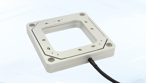
S54.T2 Tip/Tilt Stage
S54.T2 is a 2-axis piezo tip/tilt stage in θx, θy with a large aperture. It adopts a frictionless flexible hinge structure design with fast response speed and high closed-loop positioning accuracy. The 80×80mm aperture makes it easy to integrate into the systems of microscopy and scanning optical system.
Characteristics
· θx, θy tilt
· Open/closed loop
· 80×80mm large aperture
· High resolution
· Low profile
· Suitable for calibration of acceleration/angular velocity sensors
Technical Data
|
Model |
S54.T2S/K |
|
Active axis |
θx,θy |
|
Drive control |
3 driving channels,2 sensing channels/3 driving channels |
|
Nominal tilt angle(0~120V) |
±0.8mrad(≈±165”)/axis |
|
Max.tilt angle(0~150V) |
±1mrad(≈±200”)/axis |
|
Sensor |
SGS/- |
|
Resolution |
0.07µrad/0.002µrad |
|
Closed-loop linearity |
0.2%F.S./- |
|
Closed-loop repeatability |
0.1%F.S./- |
|
Push/pull force |
40N/8N |
|
Stiffness |
0.5N/µm |
|
Unloaded resonant frequency |
θx450Hz/θy400Hz |
|
Unloaded step time |
20ms/3.5ms |
|
Closed-loop operating frequency(-3dB) |
110Hz(unloaded) |
|
Load Capacity |
1kg |
|
El. capacitance |
3.6μF/axis |
|
Material |
Steel, Aluminum |
|
Dimension(L×W×H) |
125mm×125mm×20mm |
|
Aperture(L×W) |
80mm×80mm,4×R10** |
|
Mass |
510g |
**represents that the arc radius of the four corners of the light-transmitting holes is 10mm
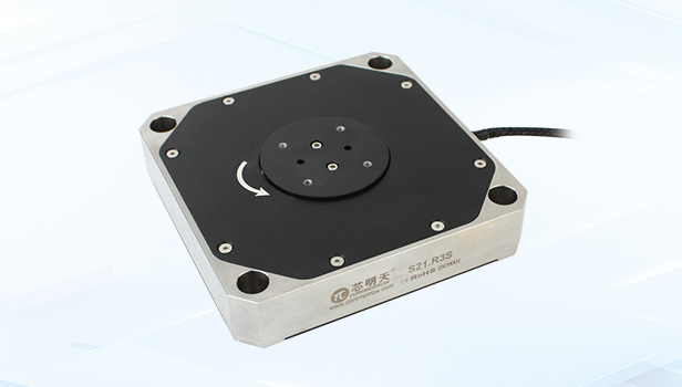
S21.R3S/K Piezo rotation stage
S21.R3S/K piezo rotation stage is a 1-axis θ-z motion piezo nano-positioning stage. It has a compact structure and is very easy to integrate.
Characteristics
· θz Rotation
· Rotation angle 3mrad
·
· Fast response speed
· Compact in size
Technical Data
|
Model |
S21.R3S/K |
|
Active axis |
θz |
|
Sensor |
SGS/- |
|
Drive control |
1 driving channel,1 sensing channel/1 driving channel |
|
Nominal tilt angle(0~120V) |
2.4mrad |
|
Max.tilt angle(0~150V) |
3mrad |
|
Resolution |
0.1μrad/0.003μrad |
|
Closed-loop linearity |
0.3%F.S./- |
|
Closed-loop repeatability |
0.1%F.S./- |
|
Unloaded resonant frequency |
700Hz |
|
Resonant frequency@0.5kg |
120Hz |
|
Resonant frequency@0.5kg |
0.5kg |
|
El. capacitance |
5.4μF |
|
Material |
Steel, Aluminum |
|
Mass(without cable) |
1635g |
For further details, please call +86-451-86268790, or add WeChat ID: 17051647888.
- Previous article:No more
- Next article:CoreMorrow Piezo Nano-Pos Stage: For HBN Single Photon Sources Research
Sweep, get the latest information on core tomorrow
Address:1F, Building I2, No.191 Xuefu Road, Nangang District, Harbin, China
Tel:0451-86268790
Piezo · Nano · Motion
